
Technology
What is actually inside
A UMAC™ Class D output stage fed by a power supply that hands watts between channels on demand; a processing chain that runs from the input connector to the driver; and a configuration interface the amplifier hosts itself. This is the long version.
- Total system power
- 500 W
- Distribution
- Lo-Z and 70 / 100 V
- Supply
- UREC™, with PFC
- Protection
- Five circuits
Where the watts come from
Four channels of UMAC™1 Class D — a full-bandwidth PWM modulator with ultra-low distortion — driven by a UREC™2 universal switch-mode supply with power-factor correction.
Full-bandwidth is the word that matters, and the conditions column is where it gets tested: signal-to-noise, distortion and frequency response are all quoted across the whole 20 Hz – 20 kHz band and into a real load, not at a convenient single frequency.
Rated output is 125 W per channel into 4 Ω or 8 Ω, with low-impedance loads from 4 Ω to 16 Ω supported. Power ratings are stated at 1% THD, at both 120 Vac and 230 Vac.
| Output power | 4 × 125 W (4 Ω / 8 Ω) · 2 × 250 W (70V / 100V) |
|---|---|
| Load range | 4 Ω to 16 Ω in Lo-Z mode |
| Output voltage | 70 Vp / 140 Vpp unloaded — bridged 140 Vp / 280 Vpp |
| Signal-to-noise ratio | > 106 dB (A-weighted, 20 Hz – 20 kHz, 8 Ω) |
| THD+N (typical) | < 0.05% (20 Hz – 20 kHz, 8 Ω, 3 dB below rated power) |
| Frequency response | 20 Hz – 20 kHz (+0 / −0.8 dB, 8 Ω, 3 dB below rated power) |
| Input impedance | 20 kΩ balanced / 10 kΩ unbalanced |
Power that moves, without a channel to give up
The supply's total output is shared automatically across each pair of output channels. When one channel briefly demands more than the amplifier's continuous rating while its partner demands less, the spare power goes to the channel asking for it — moment to moment, while the music plays.
It holds up under dynamic loudspeaker loads playing programme material, which is the load that actually asks for headroom in short bursts. It operates in low-impedance mode, across Ch 1/2 and Ch 3/4: the two pairs share independently, not as one pool of four.
The chart is a way of seeing the budget, not a picture of a control panel: nothing to configure, no split to set and no mode to choose.
Why this is not bridging
The amplifier can bridge, and does: that is how constant-voltage output works, two channels combined into one. But bridging is a trade. It halves the channel count for good — four Lo-Z outputs become two Hi-Z outputs — and it is restricted to loads of 8 Ω or higher.
Power sharing gives a channel the extra watts without asking for a channel in exchange. A four-zone install stays four zones, and the zone that needs the transient gets it.

Four low-impedance zones, or two constant-voltage lines
Output mode is set per output in the amplifier's own interface, not by a switch on the chassis and not by an external transformer. Low impedance drives the four outputs directly; high impedance bridges a pair into one 70 V or 100 V line, so the four outputs become two.
Both at once is supported, and it is what most real buildings want: a bar on a constant-voltage run, the room next to it wired low impedance, one amplifier.
In the diagram below each zone is named twice: the room, then the loudspeaker brand it is specified with — Nakymatone, Architettura Sonora, Waterfall Audio and Gray Sound, four ways of making a loudspeaker disappear into a building.
Low impedance
Four zones, one residence · 4 Ω / 8 Ω
Living room Nakymatone invisible
2 speakers · 8 Ω
Kitchen Nakymatone invisible
2 speakers · 8 Ω
Listening room Waterfall Audio glass
2 speakers · 4 Ω
Courtyard Architettura Sonora
4 speakers · 8 Ω
70 / 100 V line
Two runs, one venue · constant voltage
Main floor Gray Sound
10 speakers · 20 W taps · 200 W of 250 W
Terrace Architettura Sonora
6 speakers · 30 W taps · 180 W of 250 W
What a four-output amplifier can be configured as
Zone count and channel format follow from the input setup and the output mode. On a four-output unit:
- 2 × stereo Lo-Z zones
- 4 × mono Lo-Z zones
- 2 × mono Hi-Z zones
- 1 × mono Hi-Z + 1 × stereo Lo-Z zone
- 1 × mono Hi-Z + 2 × mono Lo-Z zones
Across the pair, not to it
A constant-voltage line is connected between the positive terminal of the first output of the pair and the negative terminal of the second. Lo-Z wiring is conventional: positive to positive, negative to negative, consistently through the install.
Keep the transformers out of trouble
A high-pass filter on any Hi-Z output avoids the distortion a line transformer produces when it saturates at low frequencies. Default 70 Hz; raise it a step at a time until the distortion is gone.
Rated at −1 dB
100 V line mode operates at −1 dB, approximately 90 V. Worth carrying into a tap budget rather than discovering at commissioning.
Everything between the connector and the driver
An input is not routed straight to an output. It passes through three stages of DSP — one that conditions the source, one that defines the room, and one that fits the amplifier to the loudspeaker — each configured independently, and the routing between them is a matrix: any input can be routed to any zone, and any zone to any output. It is the reason a four-channel box can behave like four separate systems.
- Input sensitivity — +14 / +4 / −10 dB, or mic
- Input gain
- Mono / stereo
- High-pass filter
- Five-band equalisation
- Mixing — one mix per analogue output
Four balanced or unbalanced analogue inputs and one stereo S/PDIF digital input. Of the sensitivities above, the first two suit professional balanced sources, −10 dB consumer ones, and the microphone setting dynamic microphones — there is no phantom power.
Default is +4 dBu for full output swing, with levels up to +24 dBu handled without input clipping.
Any input can be grouped with any other into a predefined mix, S/PDIF included — after the high-pass filter, the EQ and the mono/stereo decision, so what is mixed is already conditioned.
A pink-noise and sine-wave generator is built into the input stage, with adjustable gain and frequency.
- Source selection
- Priority and ducking
- Level adjustment
- Compressor
- Volume limits — minimum and maximum
- Routing restrictions
A zone is the installation's own vocabulary — a bar, a terrace, a primary bedroom — and inputs are assigned to zones rather than to outputs. Each zone carries its own level, volume limits and compressor: the tool for narrowing the gap between the loudest and quietest programme material in a room where nobody touches a volume control.
Each zone has a primary input and up to three alternatives that take over when they exceed a threshold:
- Low — advertising over background music. Threshold, attack, hold and release.
- Mid — paging. Threshold and hold.
- High — an emergency announcement; mutes everything else. Threshold and hold.
Any of them can be set to ignore the zone's volume entirely. Ducking works the same way but attenuates the primary input rather than replacing it, and adds a depth parameter.
Routing restrictions stop a given input or mix reaching a given zone at all — but not a priority input, which is correct for an alarm.
- Gain trim
- Delay
- Parametric EQ
- Crossover and gain
- Speaker EQ
- FIR — 512 taps @ 48 kHz
- Driver alignment
- Polarity
- Limiter — clip, peak, RMS
- Output mode — Lo-Z or 70 / 100 V
Zones are assigned to physical outputs here, and a stereo zone can be sent as left, right or summed mono — the summed option being what feeds a mono subwoofer or a constant-voltage line.
The speaker preset is where the amplifier is fitted to a particular loudspeaker: crossover filters with gain, parametric speaker EQ, FIR filtering, driver alignment delay, polarity, limiting and the output mode. FIR coefficients are generated externally, by speaker measurement software, and imported as a plain data file.
Presets can be built on the unit, exported, imported, collected into libraries and locked against accidental change. Preset data from a loudspeaker manufacturer imports the same way.
Limiting is three functions, engaged individually or together:
- Clip — fast or normal response.
- Peak — set manually, or tracking the crossover's high-pass setting.
- RMS — adjustable defaults, no automatic mode.
S/PDIF out, routable
Any input or zone can be routed to the stereo S/PDIF output, including inputs not assigned to a zone. A zone routed out is variable with that zone's level; an input routed out is fixed. Level defaults to −10 dB.
One source, several amplifiers
That routable digital output is what lets a single source — a central paging microphone, typically — travel through a run of amplifiers without a distribution box in the rack.
Per input, per zone, per output
None of the three stages is shared. Two zones fed from the same input can be equalised, delayed, compressed and limited completely differently — the processing after the split belongs to the zone and the output, not to the source.
The amplifier hosts its own interface
There is no software to install and no application to license. The amplifier is a network device that serves its own configuration interface — Selective Control — to a browser. Any phone, tablet or laptop on the same network can commission it.
The network can be the building's, over the rear-panel Ethernet socket or over Wi-Fi, with the amplifier taking an address automatically or holding a fixed one.
Or it can be the amplifier's own: the unit brings up a wireless access point, so a rack can be configured on the day it is racked rather than the day the site network exists. The same interface switches it over once the building network is ready.
The interface opens on a dashboard — amplifier status, output zones, and immediate access to zone volume — and everything else sits behind four tabs: Input, Zone, Output and Settings.
Settings, and the things worth knowing about
The Settings tab holds a password for the interface itself, worth setting on any amplifier reachable from a wired network. It also holds backup and restore: a configuration downloads to a file and pushes back onto the same unit or another one, which makes a multi-amplifier install repeatable rather than retyped.
Firmware is checked and updated from the same place; this page describes V1.8.0. There is also an identify function, for a rack with more units in it than labels. Wall panels and other external control devices are paired here too, each controlling a single zone or several.
Volume, standby, mute, trigger
A Euroblock GPIO connector exposes remote volume — a potentiometer above 10 kΩ, wiper to any of four pins — plus standby, mute and trigger. Pin 1 is a direct chassis ground, pin 3 a soft ground through 220 Ω: the one to reach for when an install hums. Shielded cable for switches and potentiometers.
And one caveat
The amplifier can be driven by a third-party control system API — but zone volume limits and input routing restrictions set in the web app do not apply to it. A control system can go where the interface will not.
Dante on selected models
Selected models in the range carry 4 × 4 Dante® channels on a second network socket. That socket is for Dante audio only and cannot be used for control — control stays on the primary network connection.
A pinhole, not a menu dive
Defaults can be restored from the Settings tab or, when the interface is the thing that is unreachable, from a recessed button on the underside of the chassis.
Volume and source, on the wall
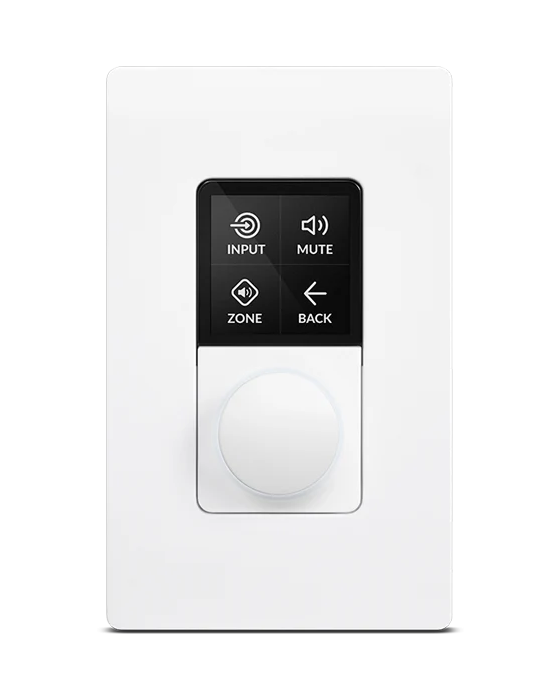
Not every zone should need a phone to turn it down. The Multi-Zone Controller is a wall plate that puts source selection and level in the room itself — input, mute, zone and back on the screen, a level knob below it.
It takes power and control from a single Ethernet run, over PoE, so there is no adaptor behind the plate and no second cable for control. That run goes back to a PoE switch or injector on the network the amplifier is already on, rather than to the amplifier itself.
One plate addresses up to eight zones. It is paired and assigned in Selective Control, in the same Settings tab as the amplifier's other external control devices — so which zones a plate reaches is a configuration decision that can be changed later, not something the wiring commits you to.
The plate is the US pattern, 71 × 115 × 43 mm.
What it needs from the cupboard
The UREC™ supply is universal — 100 V to 240 V, 50 or 60 Hz — with power-factor correction and a separate standby converter. It is a Class I product and needs an earthed mains cable.
There is no mains switch: the amplifier is operational as soon as mains is connected, so every signal, GPIO and output connection should be made before it is.
It is fan-cooled, with fan speed following temperature; in standby the fan stops entirely. Ventilation apertures are on the sides and the rear panel — keep at least 80 mm of free air behind the rear panel and 25 mm along one side, racked or free-standing.
A closed rack raises the internal ambient above the room's, and the published 0 – 40 °C operating range is measured on the amplifier, not on the wall.
Physically it is 44 × 220 × 319 mm and 2.8 kg — half a rack unit wide. Two join with a connecting plate to fill one full-width rack space, and the same hardware set mounts one under a desk or on a wall. The SD125.4 page lists it.
Standby, and what wakes it
With no input signal the outputs mute after five minutes and the amplifier drops into standby after fifteen; both delays are configurable. It wakes on an input signal, a network command, an external standby switch or a 12 V trigger — though eco standby mode switches the network off while asleep, which rules the network command out.
| Power consumption | 150 W |
|---|---|
| Idle @ 120 V | 14.5 W — 49 BTU |
| Idle @ 230 V | 15.9 W — 54 BTU |
| Standby | < 0.6 W |
| Mains | 100–240 V, 50–60 Hz, no power switch |
| Power in | 107 W |
|---|---|
| Power out | 62.5 W |
| Efficiency | 58.6% |
| Thermal loss | 44.5 W — 152 BTU |
One-eighth of full power is the conventional continuous-programme approximation; it is the figure to plan cooling against, not the 150 W.
Latency
Propagation delay is published for every input and output combination, which matters in two situations: any system where audio has to stay with picture, and any system where one signal reaches a listener by two different paths.
The digital output is tapped well before the output processing, so an analogue input leaves the S/PDIF socket in well under half the time it takes to reach the speaker terminals.
Protection and limits
Five protection circuits run continuously, and the front panel reports the amplifier's state at a glance — the five indicators and what each of them means are documented on the SD125.4 page.
The output terminals carry a CLASS 2 WIRING marking and hazardous voltage: make connections with the amplifier disconnected, and do not touch the terminals while it is powered.
| In | Analogue out | S/PDIF out |
|---|---|---|
| Analogue | 1177 µs | 458 µs |
| S/PDIF | 1833 µs | 1104 µs |
| Dante® | 1895 µs | 1166 µs |
Figures for two- and four-channel amplifiers. Dante paths apply to models carrying it.
| Circuits | Short circuit, DC, undervoltage, temperature, overload |
|---|---|
| Operating temperature | 0 – 40 °C, indoor, below 2000 m |
| Bridged load | 8 Ω or higher |
Terms
-
UMAC™ — the manufacturer’s name for the output stage: a full-bandwidth PWM modulator with ultra-low distortion, quoted here as the manual states it.
Full-bandwidth is the part that can be checked: signal-to-noise, distortion and frequency response are all quoted across the whole 20 Hz – 20 kHz band into a real load, rather than at one convenient frequency.
-
UREC™ — the manufacturer’s name for the power supply: a universal mains switch-mode supply with Power Factor Correction and a separate standby converter.
Universal means one unit for any territory — 100 V to 240 V, 50 or 60 Hz. The standby converter is what holds standby draw under 0.6 W.
The whole specification
Every figure on this page belongs to the SD125.4, the first amplifier in the range. Its product page carries the full specification table, the front-panel indicator legend, the connector list and the mounting hardware.